Ghost Flush Installation Guide
¶ What’s in the Box – NYR GHOST FLUSH®
The kit includes all the components required for installing the NYR GHOST FLUSH® invisible flush system.
Full contents of the package:
1 complete front plate with integrated keypad
4 corner brackets (2 small + 2 large)
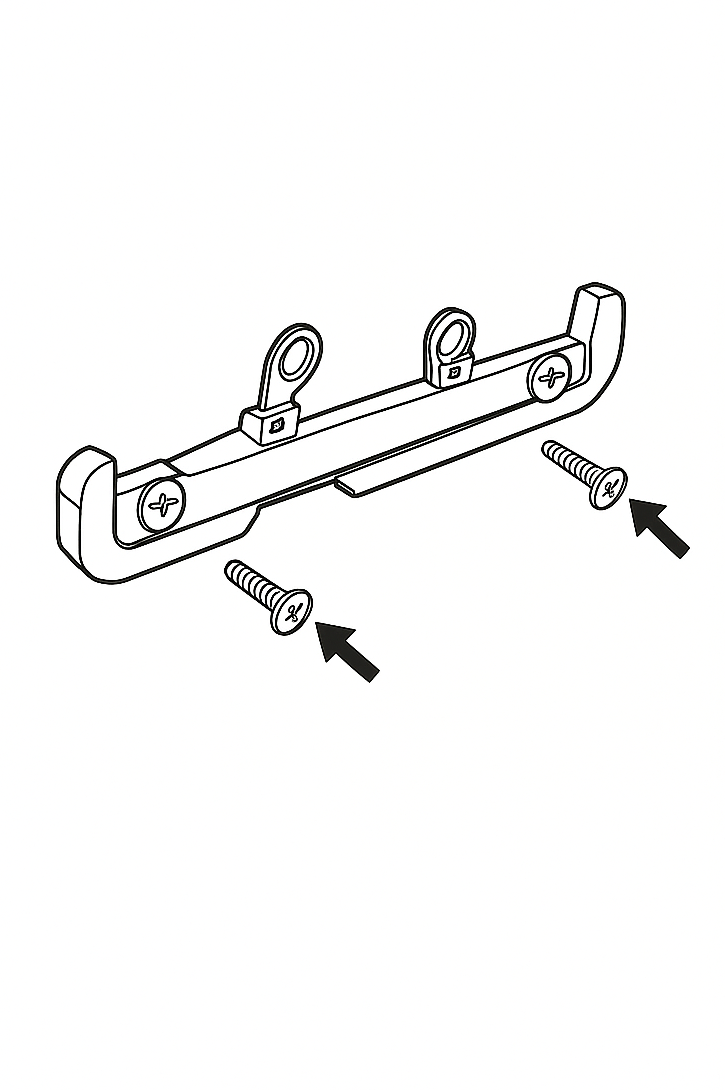
1 control screw guide
2 control screws
4 screw adapters compatible with various flush box layouts (Geberit and similar)
1 adhesive cutting stencil
¶ Requirements and Recommended Tools
To ensure precise and safe installation of the NYR GHOST FLUSH® system, the following tools and setup are required:
High-quality angle grinder
or
Compact angle drill (e.g., Proxxon or Grindex)
Fine diamond cutting disc, recommended models:
Distar Shine (for use with angle grinders)
Distar Butterfly (for use with rotary tools or compact drills)
Small-diameter diamond drill bits
(for precise pilot holes and for creating rounded corners)
Water-cooling system
Strongly recommended during cutting to prevent damage to diamond tools and ensure a clean, chip-free result.
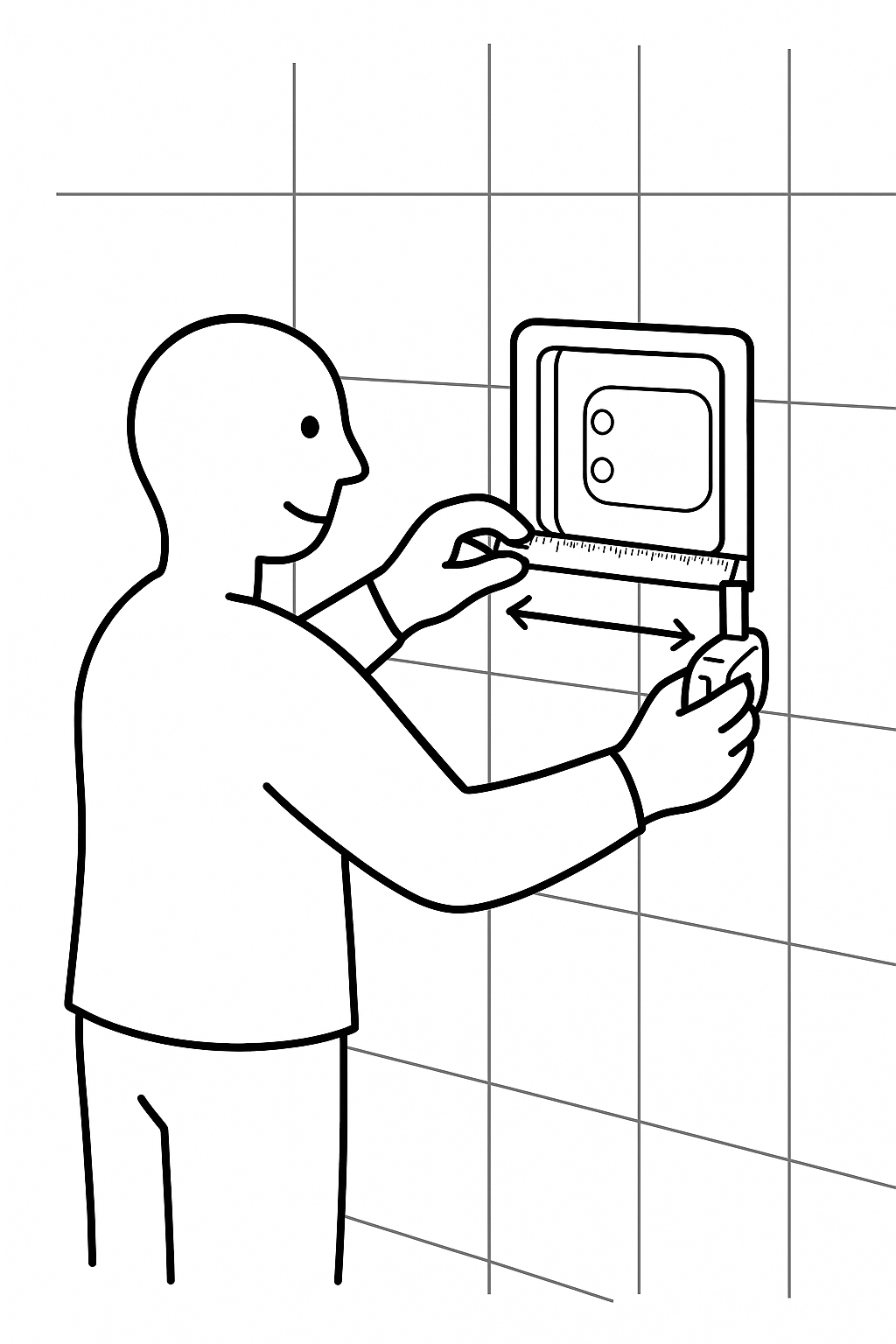
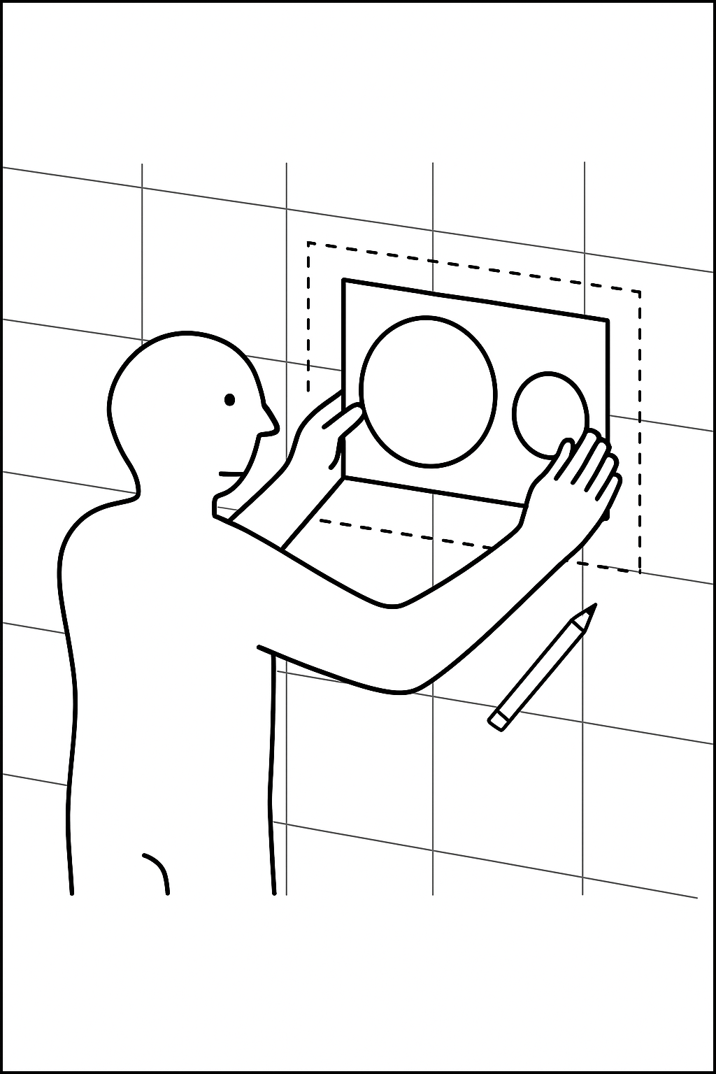
¶ Step 1 – Measure the Wall Box
Carefully measure the internal dimensions of the flush-mounted wall box. Precision at this stage is essential for correct alignment of the keypad and mounting system.
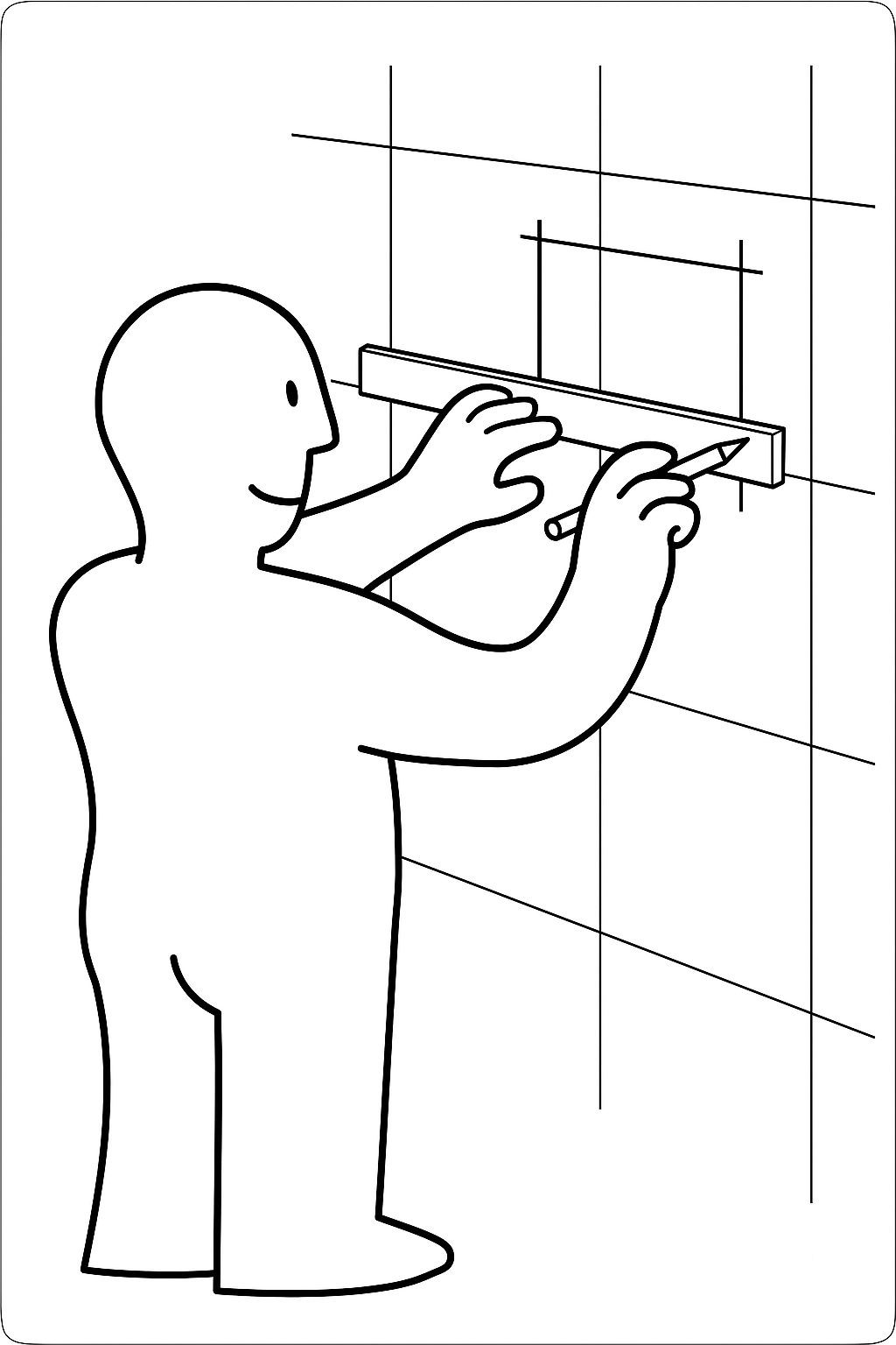
¶ Step 2 – Transfer Measurements to the Panel
Mark the precise outline on the tile where the flush system will go, using a pencil or fine-tip marker to ensure accuracy
¶ Step 3 – Apply the Adhesive Stencil
Stick the provided stencil onto the panel, aligning it precisely with the markings. Double-check before proceeding to cut.
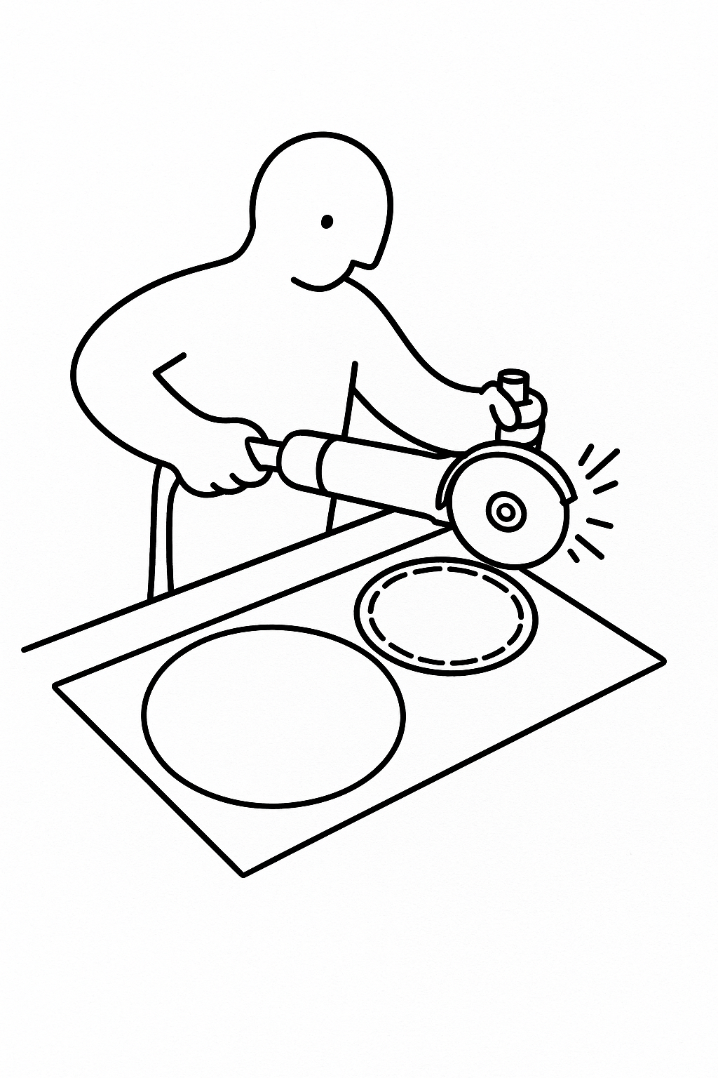
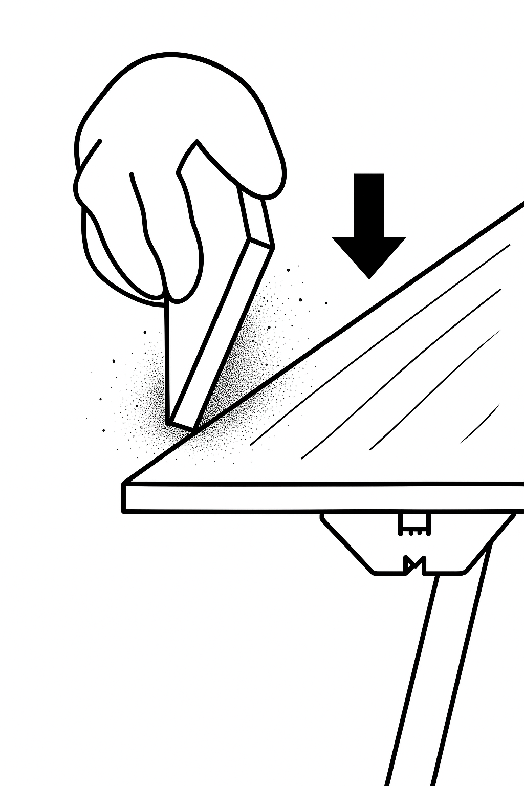
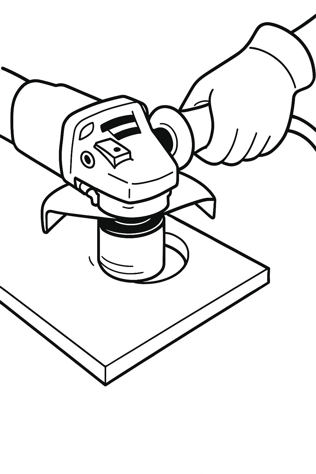
¶ Step 4 – Cut the Opening
Using a fine diamond disc and water cooling, cut along the stencil guidelines. Work slowly to avoid damaging the surface.
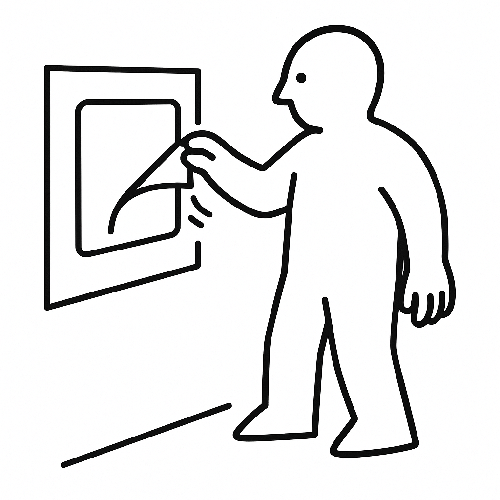
¶ Step 5 – Remove the Stencil
Once cutting is complete, carefully peel off the stencil
¶ Step 6 – Finish the Panel
Clean the cut edges. Remove any splinters or burrs using a fine abrasive pad or diamond file, ensuring smooth and safe contact points.
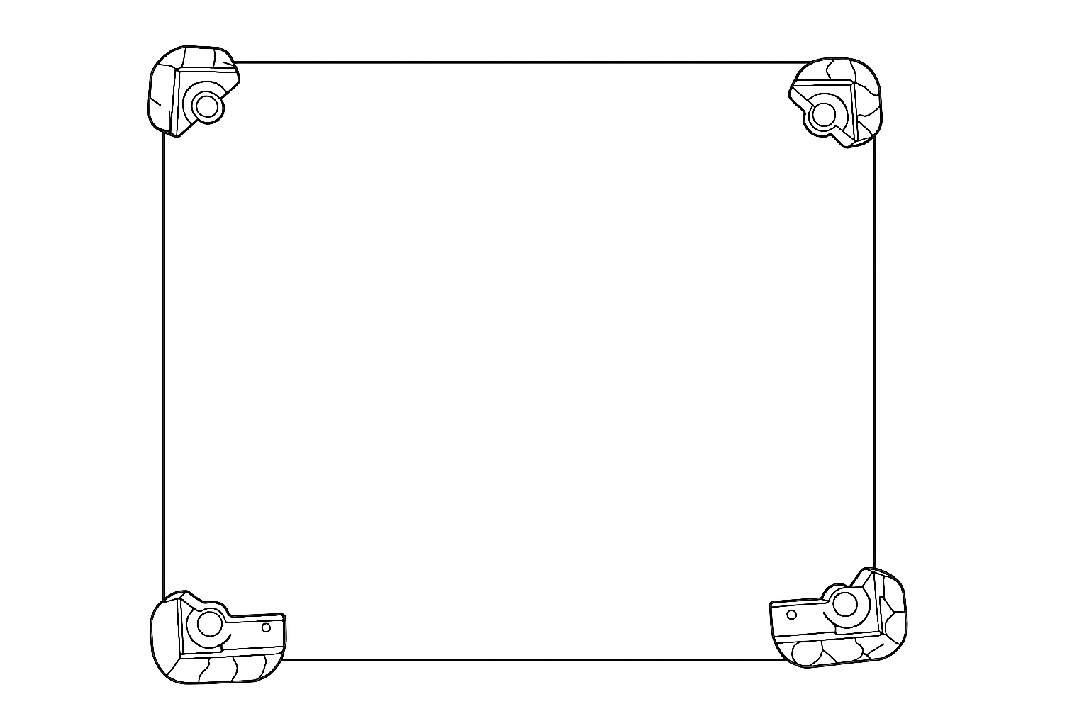
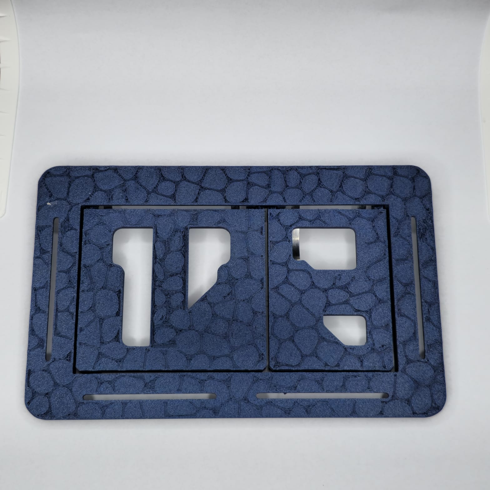
¶ Step 8 – Attach the Corner Brackets
Glue the 4 corner brackets provided in the kit to the back of the original panel.
Small brackets must be positioned at the top
Large brackets go at the bottom
Make sure the brackets are securely fixed and aligned, as they will support the entire control system.
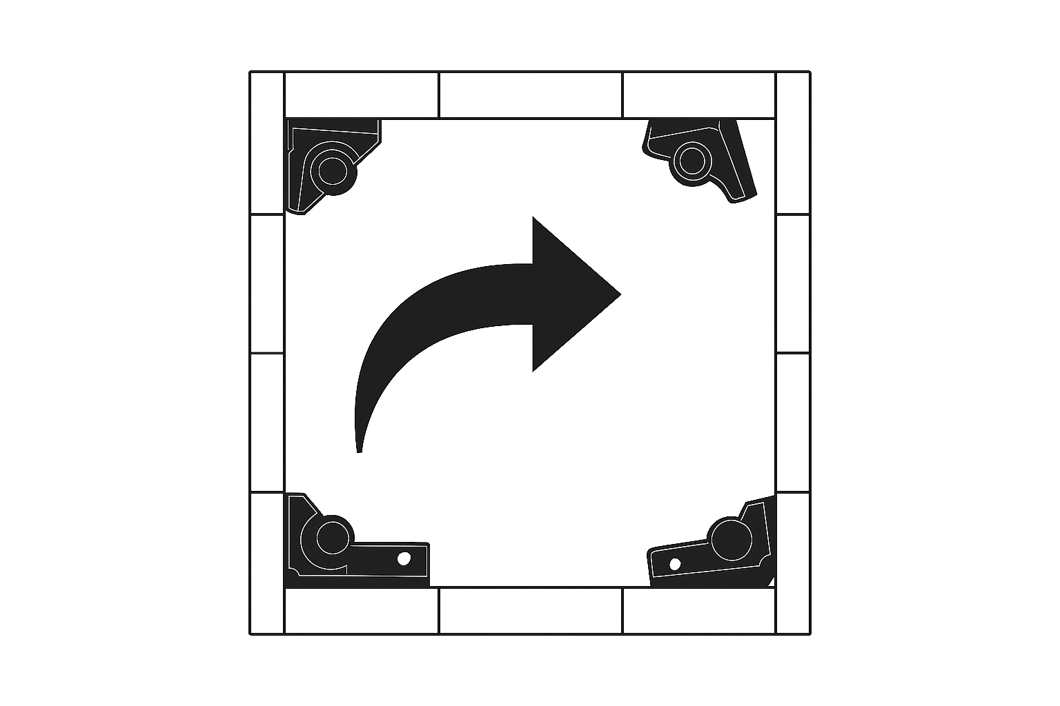
¶ Step 9 – Check the Correct Placement
Once all 4 brackets are installed, the configuration should look like this:
Two small brackets on the top corners
Two large brackets on the bottom corners
Tip: Double-check the orientation before proceeding to the next step.
¶ Step 10 – Install the Control Screw Guide
The guide comes pre-installed, but if needed, it can be easily removed and reinstalled. Insert the control screw guide between the two bottom brackets (the large ones), aligning the holes in the guide with those in the brackets.
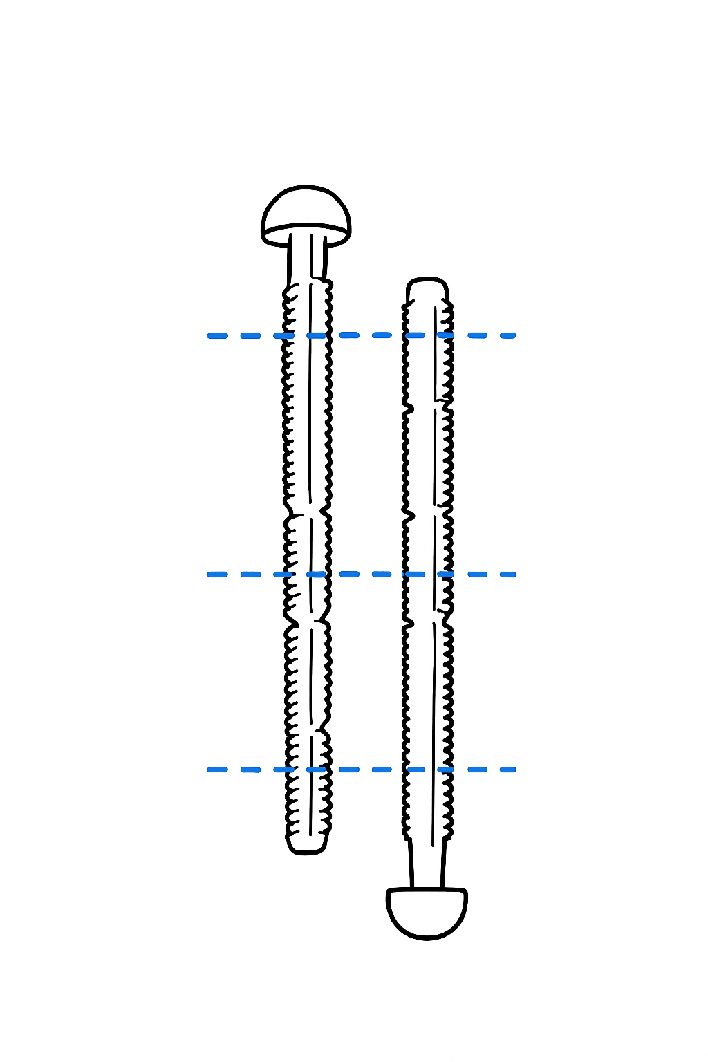
¶ Step 11 – Shorten the Screws if Needed
If the control screws are too long, they can be shortened manually.
Simply snap them at the pre-marked break points to achieve the correct length.
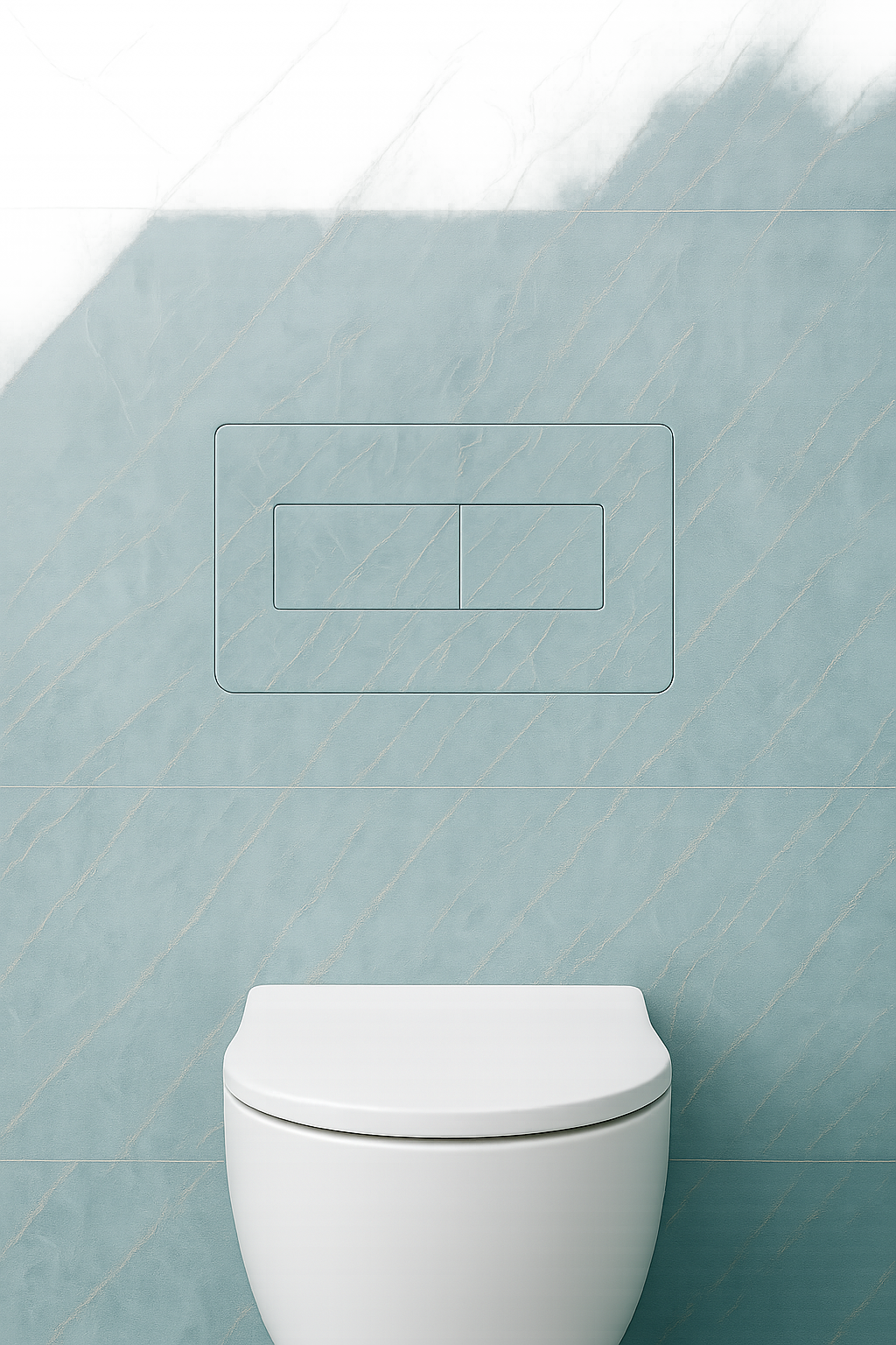
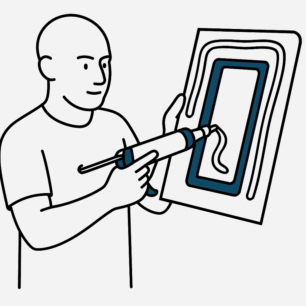
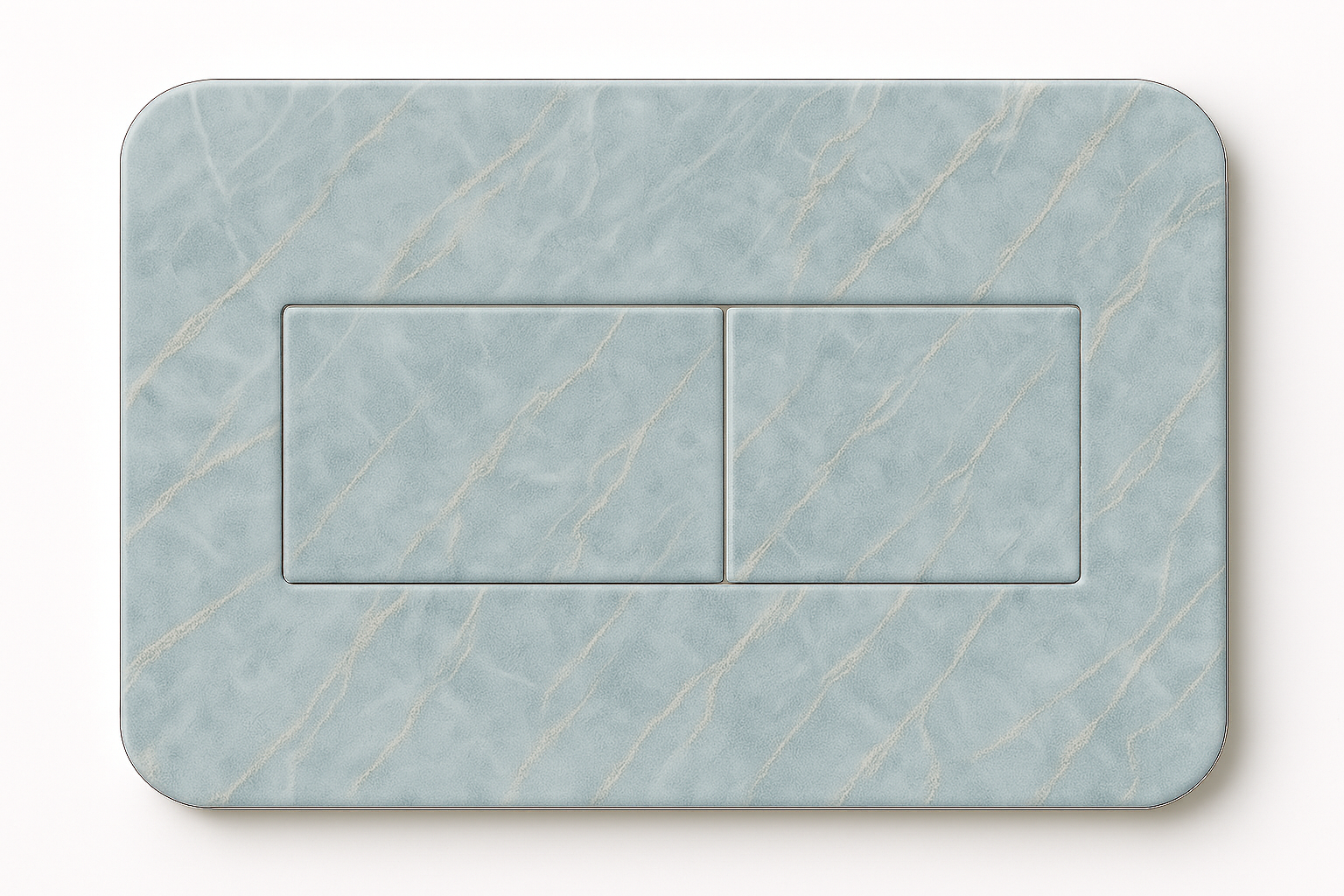
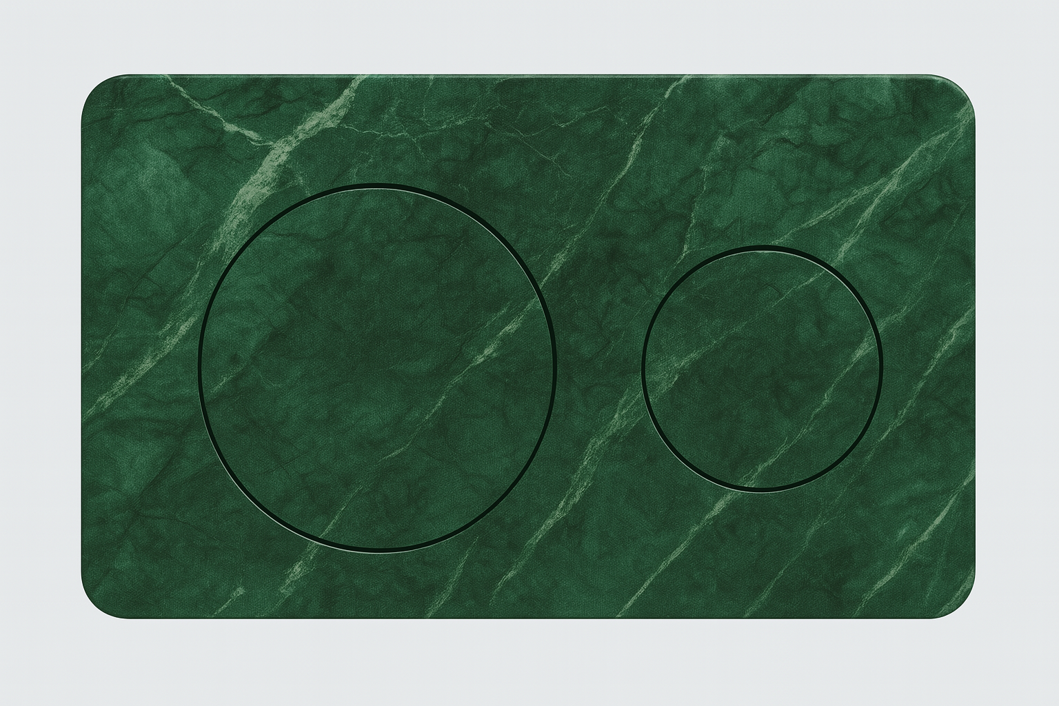
¶ Step 12 – Apply the Buttons and Plate
Using strong adhesive, glue the buttons and faceplate to the back of the panel, ensuring alignment with the cutout and bracket system.
Important: Attach to the textured side
.png)
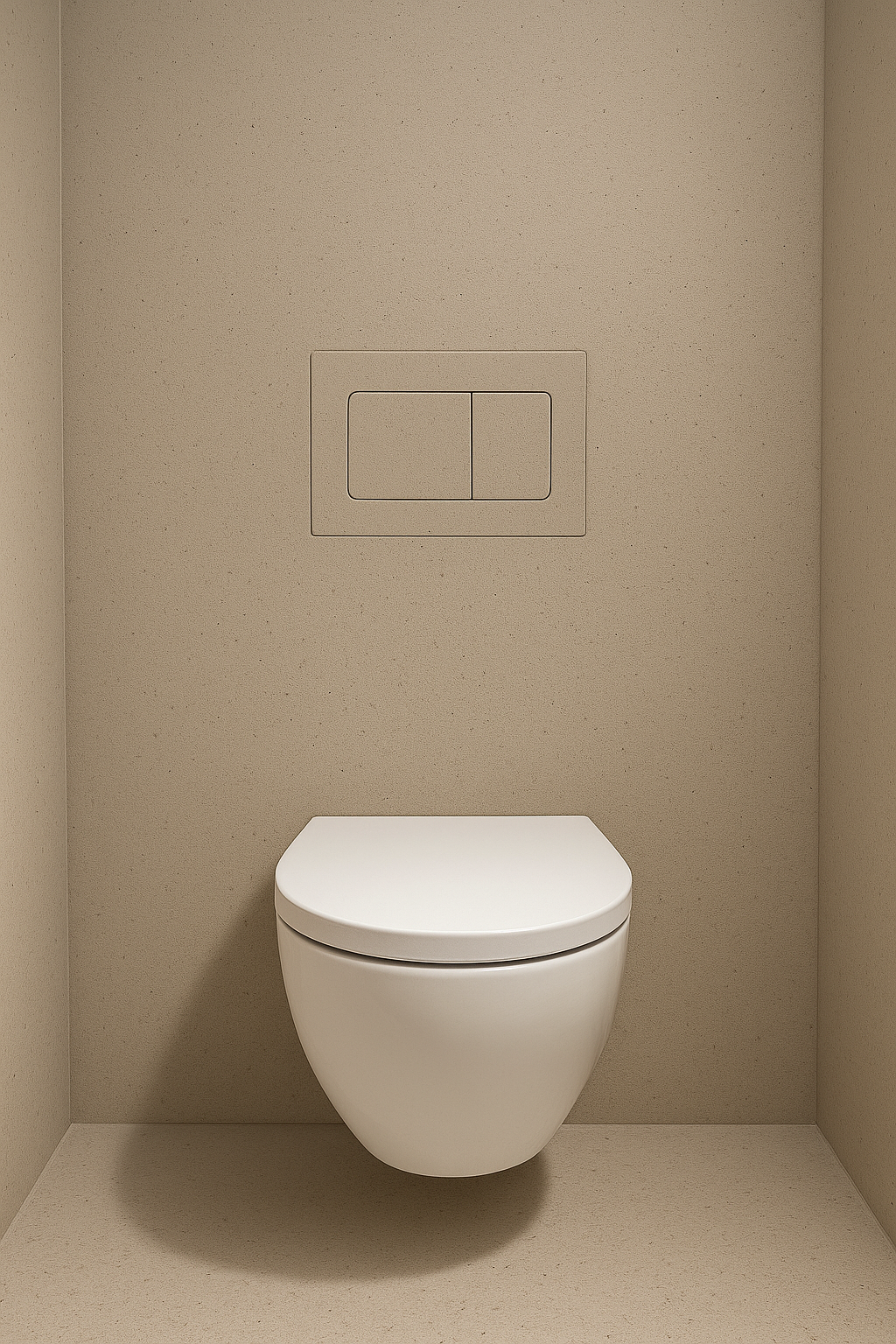
¶ Step 13 – Install the Keypad
Carefully insert the keypad into position from the front, aligning the magnets so they snap into place correctly.
Make sure the buttons are functional and return to their position with light pressure.